
I built a crossing ramp to let me get my lawn tractor across the tracks to the infield. As long as I have a crossing, I decided I need a crossing signal. What I’d really like is a set of the twin red lights that blink in an alternating pattern when the train comes, just like a real railroad. Since I can’t find anything suitable anywhere (not even eBay or Amazon), I’ll have to build my own.
The first step was figuring out how to make this happen, and determine what parts I needed. The red lights were pretty easy. Auto parts stores have generic red lights that run on twelve volts DC that can be used for my lights. I found quite a selection on Amazon. But about nine out of ten of the lights sold today are the LED lights. I wanted the older style incandescent lights just to make it look more authentic. The LED lights are instant on and instant off, while the incandescent lights glow in and glow out. These are the lights I ordered:
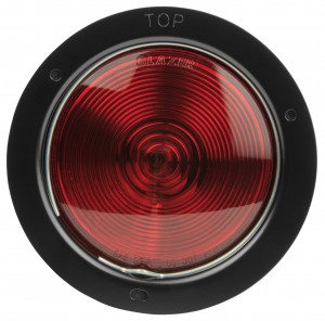
The next step was to make the black round background with the black visor. I had some aluminum flashing left over from the train house. So I cut the round background with a center hole sized to the housing for the tail lights. Then I cut a piece for the visor. Everything was attached to some scrap exterior plywood left over from the train house floor. A coat of flat black paint (I used barbecue grill paint that I had left over), and the lighting housing was ready to go.
To power the lights I purchased (again on Amazon) an exterior weather box to house the components. In order to have the lights come on when the train approaches and to blink in the proper pattern, I needed to build another computer circuit. I purchased yet another (my third) Arduino computer to handle the lighting controls.
I needed to somehow have the computer sense when the engine was in close proximity so it would know to start the lighting sequence. There are InfraRed (IR) sensors available for use with Arduino computers. But there were two problems: first, IR sensors are for measuring in inches, while I needed to get a reading when the engine was several feet away. Also, in an outdoor application, I was afraid that the ambient sunlight would include the same spectrum of IR light that the sensor was trying to read, so it would be washed out.

The alternative was to use an ultra-sound sensor. I found this HC-SR04 Ultrasonic Sensor on Amazon. It emits ultra-sonic sound waves from one of the ports, and reads the reflection from the other port. Based on the time interval from send to receive, it’s easy to calculate the distance. So I wired this sensor into my Arduino computer.

Next step was to make the lights blink in an alternating pattern. The Arduino doesn’t emit enough power to run the lights. so I needed to add a couple of relays. The computer can trigger the relay, which acts as a switch to turn a separate and more powerful circuit on and off to work the lights. I was going to use an automobile relay similar to the one I used on the engine, but then found that there are relays made for Arduino projects that are easily incorporated into Arduino circuts. This is the component I used. Note that it has four relays, while I need only two (one per light). I thought it might be prudent to have some spares, as I’ve fried a few of these components while trying to get them to work.
I programmed the Arduino computer so that it’s constantly watching for something on the track within a few feet. Once it senses that it’s there, it wakes up the relays and alternately flashes the lights for a few cycles. Then it goes back to sleep.

I put all of this, including a small twelve volt battery, into the weather housing and mounted it on the crossing sign pole. I cut two small holes in the side of the box for the sensor to look through. This makes the sensor exposed to the weather, so I don’t know how long it will last before I have to replace it. We’ll see over time. Then I plugged the Arduino into my laptop computer to calibrate the settings and hoped that it would work.

Once I had everything working, I closed up the box and ran the live test. Here is a video of everything in service:
If I can find the right type of bell, I’d like to add it to the pole and get the ding ding sound while the lights flash. But most of the bells I’ve found so far are like the school bells that ring continuously. I need one that runs on twelve volts DC that can ring with individual dings. And it needs to be weather resistant. I’ll keep looking – maybe I can get that added one day.
Update #1:
I’ve researched bells for my application. It looks like the closest thing readily available would be either a school bell or a fire bell. But these bells ring continuously. I need a bell that I can have ding just once. Then I can control the dinging with my Arduino computer.
I posted an inquiry on a hobby forum and received a response from across the country in which someone offered a bell salvaged from an old Kodak x-ray film developing machine. The bell was powered by 120 VAC, but should be able to be modified to run on a 12 VDC by removing some of the wire windings in the armature. I’m waiting on the arrival of the bell. Then we’ll see if it can be modified to run in my crossing signal. More when it develops…